Correcting Vibration is Pipes
Learn how to reduce vibration in pipes to prevent downtime and increase the lifespan of your piping.

Jon Thornham
Founder
FEA & Modal Analysis
Finite Element Analysis (FEA) and Modal Analysis are powerful techniques used in engineering to predict how products will respond to real-world forces, vibration, heat, fluid flow, and other physical effects. Autodesk Inventor and Nastran provide robust tools to perform these analyses. This article explores the concepts behind FEA and Modal Analysis and provides a step-by-step guide on how to perform these analyses using Autodesk Inventor and Nastran.
Finite Element Analysis (FEA) is a numerical method used to solve complex structural, fluid, and thermal problems by dividing the object into smaller, simpler parts called finite elements. The finite elements are interconnected at points called nodes. By solving the equations that describe these finite elements, engineers can predict how a product will behave under various conditions.
FEA is used in various fields, including:
1.
Mechanical Engineering: To analyze stress, strain, and deformation of mechanical components.2.
Civil Engineering: For structural analysis of buildings, bridges, and other infrastructures.3.
Aerospace Engineering: To evaluate the performance of aircraft and spacecraft structures.4.
Automotive Engineering: For crash simulations and durability studies.Modal Analysis is a specific type of FEA that focuses on determining the natural vibration characteristics of a structure or component. It identifies the natural frequencies, mode shapes, and damping characteristics. This is crucial for understanding how a structure will respond to dynamic loads and vibrations.
Modal Analysis is commonly used in:
1.
Design Optimization: To avoid resonant frequencies that could cause excessive vibrations and potential failure.2.
Noise, Vibration, and Harshness (NVH) Analysis: In automotive and aerospace industries to improve comfort and performance.3.
Structural Health Monitoring: To detect and diagnose damage in structures based on changes in their modal properties.Let us help you avoid vibration by providing an engineered solution using modal analysis.
Autodesk Inventor provides a user-friendly environment for CAD modeling, while Autodesk Nastran, integrated into Inventor, offers advanced FEA capabilities. Below is a step-by-step guide to performing FEA and Modal Analysis using these tools.
1.
Start Autodesk Inventor: Create a new part or assembly.2.
Model the Geometry: Use Inventor's robust modeling tools to create the geometry of the part or assembly you wish to analyze.3.
Assign Material Properties: Ensure that the correct material properties are assigned to the model, including density, Young’s modulus, and Poisson’s ratio.1.
Switch to the Nastran Environment: In Inventor, go to the Environments tab and select "Nastran In-CAD".2.
Create a New Study: Choose the type of analysis you want to perform (e.g., linear static, modal, thermal, etc.).3.
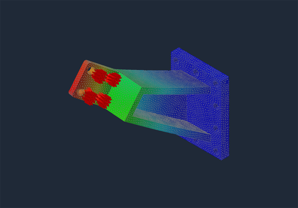
Define the Mesh: Set up the mesh parameters and generate the mesh. The mesh quality can significantly impact the accuracy of the results. Finer meshes generally yield more accurate results but require more computational resources.4.
Apply Loads and Constraints: Specify the boundary conditions, loads, and constraints. For example, fix certain faces, apply forces, pressures, or other loads.1.
Run the Solver: Start the analysis by running the Nastran solver. Monitor the progress and ensure there are no errors in the setup.2.
Review Results: Once the analysis is complete, review the results. For FEA, this includes stress, strain, displacement, and other relevant outputs. For Modal Analysis, focus on the natural frequencies and mode shapes.1.
Stress and Strain Analysis: Check if the maximum stress is within the allowable limits of the material. Identify potential failure points and areas of high stress concentration.2.
Displacement Analysis: Ensure that the deformations are within acceptable limits.3.
Modal Analysis: Evaluate the natural frequencies and mode shapes. Ensure that the operational frequencies do not coincide with the natural frequencies to avoid resonance.1.
Optimize the Design: Based on the analysis results, make necessary design changes to improve performance and safety.2.
Re-Analyze: Repeat the analysis with the updated design to verify the improvements.1.
Model Simplification: Simplify the geometry as much as possible without compromising the accuracy of the results. This reduces computation time and resources.2.
Mesh Quality: Use an appropriate mesh size and type. A finer mesh near critical areas can improve accuracy.3.
Validation: Always validate your FEA results with experimental data or theoretical calculations when possible.4.
Documentation: Document all assumptions, boundary conditions, and material properties used in the analysis for future reference.Finite Element Analysis and Modal Analysis are essential tools in modern engineering, allowing for the accurate prediction and optimization of product performance. Autodesk Inventor and Nastran provide a powerful and integrated platform for performing these analyses. By following the steps outlined in this guide, engineers can leverage these tools to create safer, more efficient, and reliable products.
This article provides a comprehensive overview and a practical guide for performing FEA and Modal Analysis using Autodesk Inventor and Nastran. Whether you are a beginner or an experienced engineer, these tools can significantly enhance your design and analysis capabilities.
If you are seeing vibration issues on motors, fans, piping, turbines, or structural systems, this article covers only one piece of the diagnostic process. Our comprehensive Vibration Analysis and Engineered Correction guide shows how we use modal testing, ODS, FRFs, FEA, and field measurements to identify root causes and engineer permanent fixes.
Learn how to reduce vibration in pipes to prevent downtime and increase the lifespan of your piping.
Jon Thornham
Founder
Author Details
Founder
Jon Thornham is the founder of Vibration Engineers, a professional mechanical engineer, and entrepreneur focused on solving complex vibration and reliability challenges across industrial sectors.